(Basically, this means that devices such as IP cameras, Access Points and VOIP phones is powered through the Ethernet cable to which it is connected too, which also gives the devices direct network access.)
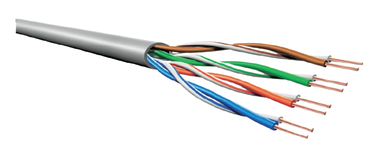
(UTP) Unshielded Twisted Pair cable
Two (2) cores are twisted forming 4 pairs.
On a 10BASE-T and 100BASE-T Ethernet system two pairs (the orange pair and the green pair) are used for Ethernet communications.
The other two pairs (blue pair and brown pair) are not used at all
To send Power over the Ethernet cable, the two unused pairs is now used to transmit power. The blue pair for the positive polarity and the remaining brown pair for the negative polarity of the DC (Direct Current) supply.
( We know this does not line up with standard electrical colour codes, but that is the standard on Ethernet networks )
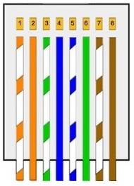
Typical wiring of an RG-45 Plug where PoE is implemented:
| 1 | used to transmit Data + | TX + |
| 2 | used to transmit Data - | TX - |
| 3 | used to recieve Data + | RX + |
| 4 | used to transmit the positive polarity of power | |
| 5 | used to transmit the positive polarity of power | |
| 6 | used to recieve Data - | RX - |
| 7 | used to transmit the negative polarity of power | |
| 8 | used to transmit the negative polarity of power |
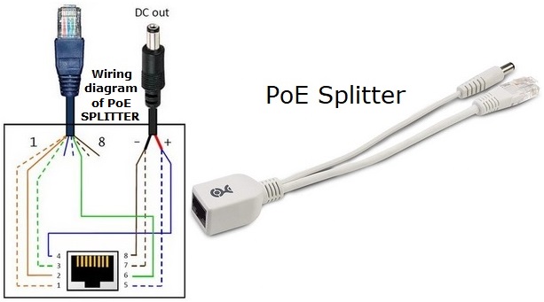
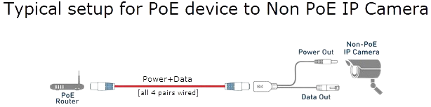
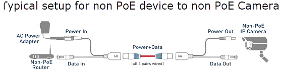
The female RG-45 connector receives the PoE Ethernet cable, then splits it to data only out on the RG-45 male connector, and DC on the male DC power jack.
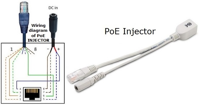
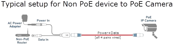
The PoE injector is used to inject power onto the Ethernet cable.
Power goes into the female DC power jack, and the data goes into the male RG-45 connector.
Then full PoE comes out of the female RG-45 connector.